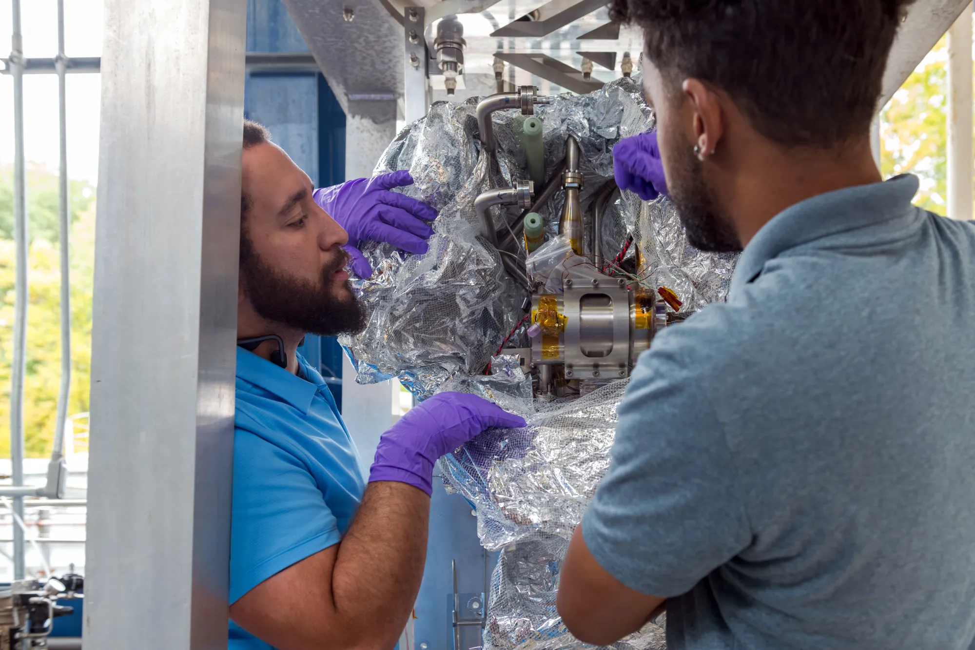
B. Hansen and G. Tatkowski
Pulse tube cryocoolers are integral to current dilution refrigerator (DR) technology, which are often referred to as “dry” DRs. In this application, the cryocoolers are used to cool the two highest temperature stages of the DRs to approximately 45 K (stage 1) and 3 K (stage 2) and are integral to the precooling process of the 3-He dilution circuit, required to achieve the ultra-low temperatures of the dilution unit in the millikelvin range [1, 2]. It wasn’t always this way. DR technology started as “wet” systems with liquid helium and liquid nitrogen transferred directly into the DR, where they provided cooling at a 77 K and 1 to 4 K stages. These systems required regular cryogen deliveries, open handling of liquids, and active management of boil-off, etc. which led to high operational overhead and safety complexity. The integration of cryocoolers into dilution refrigerators in the early 1990s represented a major technological improvement by simplifying their construction and operation from wet technology (liquid cryogen cooled) to dry technology (cryocooler-based) (Figure 1 a,b) [3, 4]. Since that time, the DR industry has seen significant growth, largely driven by the acceleration in quantum computing, quantum sensing, and quantum networking R&D in both academia and industry. As quantum computing technology continues to advance from lab-based, benchtop experiments with 10s of qubits cooled within a single DR to fault-tolerant, datacenter quantum computers that will require 100-1,000 kQubits hosted within 100s-1000s of DRs [5, 6], the optimal cooling scheme of the high-temperature stages of DRs is being revisited and may evolve toward quasi-wet technology (Figure 1c).
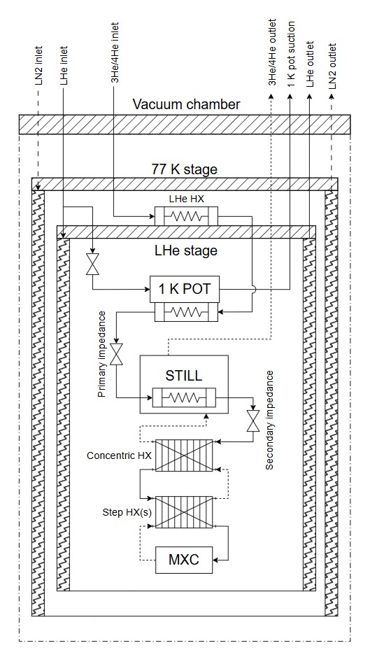
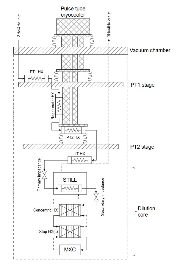
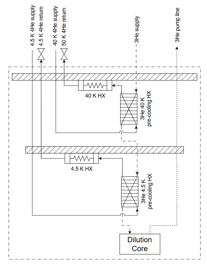
Figure 1: Process flow schematics for (a) traditional Wet DR ; (b) Dry DR and (c) conceptualized quasi-wet DR for future datacenter scale quantum computers.
At the single-system level, pulse tube cryocoolers remain compelling. They offer turnkey operation, eliminate liquid cryogen handling, and provide sufficient cooling power at 45 K and 3 K for most laboratory-scale heat loads. However, as systems expand towards datacenter scale quantum computers that could require 100s-1000s of DR cryostats, the aggregate energy, cost, and operational penalties of distributed cryocoolers become increasingly significant. A DR typically requires multiple cryocoolers, each with its own compressor, power electronics, vibration mitigation, and maintenance schedule. When multiplied across hundreds of systems, this results in a highly fragmented cryogenic architecture with limited economies of scale and rapidly growing infrastructure overhead.
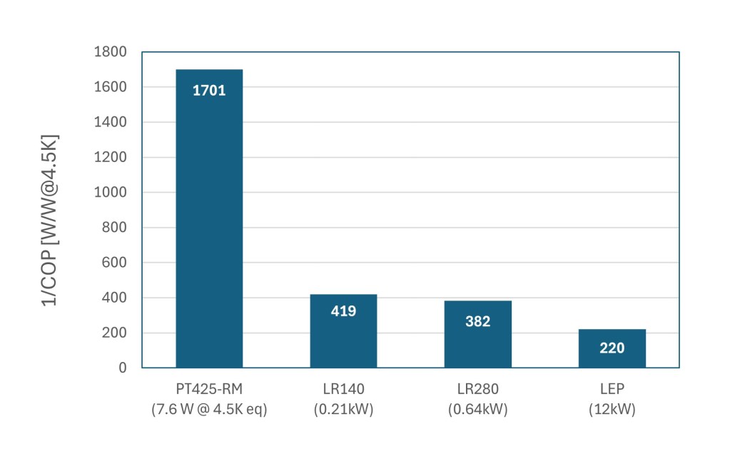
Industrial-scale helium cryogenic plants (cryoplants) fundamentally change this equation. Large, centralized refrigerators benefit from higher efficiencies, resulting in a substantially lower inverse coefficient of performance (1/COP), a number that represents how many watts of electrical power are required to provide 1 W of refrigeration at a given temperature. Industrial scale cryoplants have a 1/COP range of ~250-450 W/W at 4.5K and ~5 W/W at 77K which scales with cooling capacity [7, 8]. By comparison, state-of-the-art cryocoolers such as Cryomech’s PT425 have a plug power of 13 kW and provide 2.7 W of refrigeration at 4.2 K and 55 W at 45 K [9]. This corresponds to a 1/COP of approximately 1700 W/W at 4.5K equivalent, which is more than four times higher than that of industrial scale cryoplants (Figure 2). The equivalent 4.5 K capacity for the PT425 is estimated by scaling the refrigeration capacity at a given temperature stage by the ratio of the ideal Carnot efficiencies at that temperature and at 4.5 K [10].
As systems scale up, the electrical cost savings become significant, providing an attractive return on investment. For example, a system of 100 dilution refrigerators each utilizing two PT425 cryocoolers per DR (2.6 MW total plug power) would require ~2 MW more electrical power than a centralized cryoplant optimized to serve the same combined load. In addition, aggregating the cooling demand across systems enables more efficient use of utilities, such as cooling water and electrical power distribution, yielding system-level efficiency gains that grow with scale.
Beyond thermodynamic efficiency, centralized cryoplants providing closed loop, forced-flow cooling, would enable more effective heat-load management across multiple temperature stages within DRs. As these new quasi-wet DRs are reimagined, they are no longer geometry limited by the cryocooler cold head and its heat transfer surface area. Instead, the forced flow helium piping can bring the cooling directly to wherever it is needed and enthalpy recovery between temperature stages becomes more practical, providing further opportunity for optimization.
Designing the cryogenic distribution system that connects a central cryoplant to hundreds of DRs brings its own set of technical challenges. The distribution system must efficiently deliver stable, low-vibration cooling at multiple temperature levels while also accommodating long distances, variable loads, and frequent connection points. Pressure drop management, flow balancing, thermal acoustic oscillation mitigation, and thermal contraction will become increasingly complex as the DR array grows and the transferline branching increases. Additionally, the system must be segmented in such a way to provide partial operation, allowing individual or smaller groups of DRs to be installed, isolated, removed, and serviced without disrupting the broader fleet. This segmentation is analogous to the cryogenic distribution systems being designed for PIP-II [11] and already in operation at other superconducting accelerators [12].
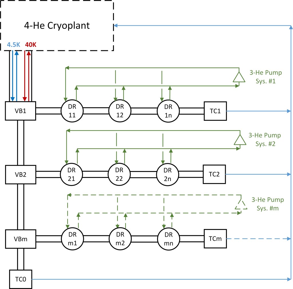
A process flow scheme for an array of DRs cooled by a central cryoplant is illustrated in Figure 4. Here you have an array of m x n DRs arranged in segments with cryogens distributed via a series of Valve Boxes (VBs) and Turnaround Cans (TCs) connecting the supply and return of the 4.5K and 40K cooling circuits. Optimization and layout of the DR array segmentation and the internal DR cooling schemes will require a combination of analysis and experimentation with close partnership with industrial stakeholders. In Illinois, a strong foundation of quantum computing initiatives and enabling infrastructure is already in place. Most notably at Fermilab through the SQMS Center and the Cryogenic Technology Division, which has a long track record of national leadership in quantum computing R&D and large-scale helium cryogenics, respectively. Coupled with growing industry partnerships, Fermilab is well positioned to make major contributions to accelerating data-center quantum technology [13,14]. In addition, the University of Illinois’ Illinois Quantum and Microelectronics Park (IQMP) is designing a large-scale helium cryogenic system as part of their National Quantum Facility (NQF), which is a purpose-built system to support quantum computing R&D efforts [15]. This momentum was underscored during the recent House Committee hearing on Assessing U.S. Leadership in Quantum Science and Technology, where Rep. Foster noted that “One of the joys of representing Illinois is I get to brag about how Illinois has been a real national focal point for the development of quantum science and quantum computing. The entire state actually has become a proving ground for the field.”
In addition to centralizing the 4-He cooling system, there may also be opportunities to partially centralize the 3-He gas handling and pumping system to further improve facility efficiency, operation and maintenance. By combining pumping functions such as roughing capacity, or shared vacuum skids into centralized locations, meaningful reductions in capital cost, floor space, heat rejection, and maintenance overhead could be realized compared to fully distributed one pump train per DR architectures. Partial centralization also enables more efficient operation through pump staging and variable-speed control, so that pumps run closer to optimal efficiency during different operating states. The primary tradeoff is the added system complexity and the risk introduced by a shared 3-He pump system. For example, shared pumping stages can introduce transient coupling between refrigerators with operations and events such as pump down, 3-He leaks, or operator errors on one DR can disturb header pressure and impact other DRs unless isolation is fast and reliable.
Availability is another critical consideration as quantum computing infrastructure evolves toward true datacenter operation which requires advanced levels of reliability. Centralizing the 4-He and 3-He systems further concentrates single point failures. A compressor skid trip, power loss, or control system fault can affect multiple DRs raising availability requirements, driving the need for segmentation, redundancy, robust interlocks, and clearly defined fault modes. Systems will need to be configured with N+1 or N+2 redundancy in critical areas to achieve Tier 3 data center reliability (>99.942%). In addition, liquid buffer volumes configured for automatic recovery strategies may be utilized to further enhance system availability and fault ride through, protecting sensitive quantum hardware from rapid thermal excursions.
In summary, while pulse tube cryocoolers enabled the rapid expansion of dilution refrigerator technology over the past two decades, the transition to large-scale quantum systems is now driving a reassessment of the higher-temperature-stage cooling strategies of DRs and how these systems can be effectively scaled in a modular way. Quasi-wet architectures based on centralized cryoplants and forced-flow helium distribution offer compelling advantages in energy efficiency, operational cost, and scalability. With appropriate redundancy, standardized interfaces, and optimized distribution system designs, these architectures can provide a practical and robust path forward for the next generation of quantum computing infrastructure.
References:
[1] Zhao, D.Z., & Wang, D.C. (Eds.). (2019). Cryogenic Engineering and Technologies: Principles and Applications of Cryogen-Free Systems (1st ed.). CRC Press. https://doi.org/10.1201/9780429194726
[2] Pobell, F. (2007). Matter and methods at low temperatures (3rd ed.). Springer Berlin Heidelberg
[3] Pari, P. (1990). Dilution Refrigerator with No Liquid Helium Supply. In: Fast, R.W. (eds) Advances in Cryogenic Engineering. Advances in Cryogenic Engineering, vol 35. Springer, Boston, MA.
[4] Uhlig, K., & Hehn, W. (1994). 3He/4He dilution refrigerator combined with Gifford–McMahon cooler. Cryogenics, 34(7), 587–590
[5] Bernhardt, J-M., Martin, F., Szmigiel, M., “Development of cryogenic infrastructures for quantum computing”, (2025) Cryogenic Engineering Conference, C1Or2C-01
[6] Mohseni, Masoud, Scherer, Artur, Johnson, K. Grace, et al., “How to Build a Quantum Supercomputer: Scaling from Hundreds to Millions of Qubits, (2024)
[7] Monneret, et. al. (2015). “ITER Cryoplant Status and Economics of the LHe plants.” Physics Procedia 67: 35-41.
[8] T. R. Strobridge, “Cryogenic Refrigerators: an Update Survey”, NBS Technical Note 655 (1974).
[9] https://bluefors.com/products/pulse-tube-cryocoolers/pt425-pulse-tube-cryocooler/
[10] Liu, Xiaogang, Lilong Qiu, Junjun Li, Zhaoliang Wang, Yong Ren, Xianwei Wang, Guoqiang Li, Xiang Gao, and Yanfang Bi. “Conceptual Design of the Cryogenic System and Estimation of the Recirculated Power for CFETR.” Nuclear Fusion 57, no. 1 (2017)
[11] Martinez, A., J. Creus Prats, W. Soyars, R. Dhuley, B. Hansen, Y. Jia, A. Chakravarty, M. Goyal, and T. Banaszkiewicz. (2024). “Overview and Status of the PIP-II Cryogenic System.” IOP Conference Series: Materials Science and Engineering 1301 (1): 012106.
[12] W. Schneider, et al, “Design of the SNS Cryomodule,” PAC’01, Chicago, June, 2001.