by Harrie Vermeulen, DH Industries USA Inc., h.vermeulen@d-h-industries.us
![]() Cryogenic gas circulators (CryoFans) are not very well known in the industry as a possible solution for cryogenic process design. In case a complex system needs to be cooled and a direct connection of a cryocooler is impossible, difficult or causes other issues, such as vibration, a gas circulator might solve the problem.
Cryogenic gas circulators (CryoFans) are not very well known in the industry as a possible solution for cryogenic process design. In case a complex system needs to be cooled and a direct connection of a cryocooler is impossible, difficult or causes other issues, such as vibration, a gas circulator might solve the problem.
With a gas circulator, a system designer can thermally connect an application to a remote cryocooler by flowing a gas as thermal fluid. Typically helium gas is used in the temperature range of 100 to 10K. This immediately shows the beauty of these systems: Almost all required temperatures can be achieved, allowing the designer to go as high in temperature as the application allows for, giving more freedom and flexibility in the design.
A cryogenic gas circulator is nothing more than a gas pump that “gets the gas flowing,” transporting the heat (energy) created by an application to the cryocooler which in turn removes this heat from the system.
As with most pumps, flow and pressure drop are the main specifications, and seem pretty straightforward. However, as we are dealing with cryogenic temperature gas, instead of, for instance, an ambient T liquid, things like density (mass flow), efficiency, thermal insulation, maintenance and the fact that cooling capacity is limited/expensive, become huge factors in the pump design and selection.
 Figure 1 shows a simplified process design of a gas-cooled system. Item 1 is the customer’s application. This is shown as a black box (gray cylinder), but it can be anything that is required to operate at a cryogenic temperature, generating X amounts of watts. It can be a high temperature superconducting (HTS) device (motor, generator, cable), a magnet, a space simulation chamber, etc. Sometimes this application is also visualized as a heat exchanger.
Item 2 is the gas circulator (CryoFan). By connecting all of the components, a loop is created with pressurized helium as transfer media. By switching on the cryocooler and the gas circulator, the helium gas becomes cold and is pumped through the application and cools it as the gas is heated/absorbs energy. The warmer gas is then transported to the cryocooler where this absorbed energy will be removed and the loop is closed.
Item 4 is a heat exchanger that connects to the selected cryocooler. Cryocoolers typically have a copper flat plate which provides the cooling power. In case of liquefaction of a gas or by direct contact, this is fine, but when trying to cool a gas stream an optimized heat exchanger is required to guide the gas over the cold head with enough surface area. This will allow for a heat flow between the gas being cooled and the cold head.
For this application, heat exchangers typically made of copper are designed to be mounted on the cryocooler—or they can be an integral part of the cold head. Not shown in Figure 1 is the cryostat/vacuum space which will contain all or most of the equipment for thermal insulation.

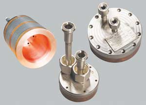
CryoZone also supplies a range of heat exchangers (HX; see Picture 2) which are specifically designed for common commercially available cryocoolers, such as the Cryomech 300 series, AL60, Sumitomo 415D, Helix, etc. These heat exchangers are designed to match, and be bolted to, the cold head and allow for a heat exchange that meets that specific cooler capacity.

Process design considerations
Designing a closed loop helium gas circulation system will require ample consideration and some compromise, as the whole process is a delicate balance. Changing one parameter can shift the complete balance, as all parameters interact and influence each other. Let’s look at the main considerations.
Working pressure
First, a working pressure of the helium gas needs to be selected. All components in the closed loop have to be designed to withstand that pressure. Although a thermal balance generally is based on mass flow, a CryoFan and also the interconnection piping are selected on volume flow. Besides temperature, the volume of the gas depends on the pressure, which determines the density. The higher the gas pressure, the smaller the volume flow will be at equal mass flow. Also the flow resistance in the equal diameter piping will be lower and the CryoFan can be smaller. This design is favored because it will require less heat input both static and dynamic and it will be cheaper.
The CryoFans and heat exchangers have a design pressure of 30 bara (435 PSIA).
So, from a CryoFan point of view, it is advisable to select the highest pressure possible.
Pressure drop (dP)
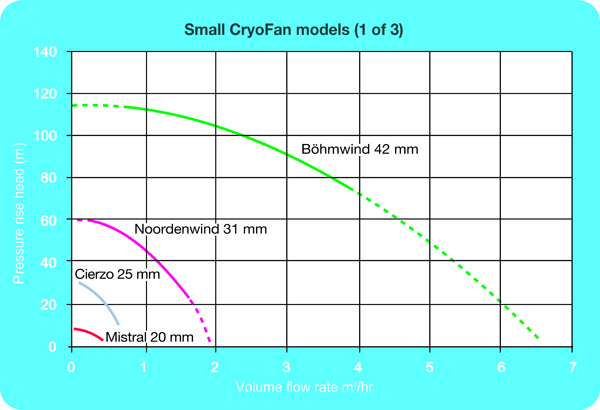
Designing the correct pressure drop of a system also requires a subtle approach: CryoFans are designed as centrifugal pumps. As they pump only low density gas, they are not able to overcome high pressure drops. Typically the available pressure rise is expressed in meters head in a fan curve.
The available pressure drop (in Pascal) = available head (in meters) * density of the gas (in kg/m3) * gravity (in meter/sec2) (equation 1).
As the available pressure drop is low, a good balance and design needs to be found between the components creating this dP, within the application itself and also in the interconnecting tubing. Small tubes might be favored because of price, available space, service area or heat leak, but small tubes will have high pressure drop at a determined volume flow. For the heat exchanger on the cryocooler, we would ideally like to have infinite surface area in order to get the best heat transfer. This can be achieved by very long, very small tubes. But, again, that will create too much pressure drop. So the HX will—most of the time—also be a compromise between performance and pressure drop limitations.
Temperature profile / allowable delta T (dT)/ heat balance
As the cold helium gas coming from the cryocooler flows through the system, it will heat up. This is caused by several factors:
1. Heat leak (conduction) from the outside and through the materials of the CryoFan into the system.
2. Labor: in order to “get the gas moving,” the CryoFan will put energy in the gas to overcome the friction of the system (Volume flow * dP). This energy will heat up the gas. Although the labor is provided by the CryoFan and depends on the efficiency/pump curve of the fan, this energy does not “show up” at the CryoFan. It will show itself as a temperature increase across the whole system, specifically at the high pressure drop (restricted) areas. This dT is on top of the temperature increase that the application is creating.
3. Inefficiency of the CryoFan: A pump cannot be 100 percent efficient. The CryoFans can achieve an excellent efficiency of over 50 percent. However any inefficiency will be put into the gas, directly at the CryoFan, heating the gas from the inlet to the outlet.
4. “The application”: Usually this is the largest contributor, and it can consist of several of the items mentioned above.
Point 1 above is called the static losses of a CryoFan.
Point 2 and 3 above together are called the dynamic losses of a CryoFan.
Once the gas has completed its loop through the heat exchanger, CryoFan, piping and application, it will return at the cryocooler X degrees warmer. This temperature difference is referred to as the delta T (dT) of the system: X (dT in K) = Q (total watts produced) /(mass flow in kg/sec * specific heat of the gas in Joule/(Kg*K)) (equation 2).
Normally the operating temperature and allowable dT is dictated by the application: the highest T allowed at the outlet of the application and how stable/homogenous the T profile across the application has to be. The latter is the dT in abovementioned equation 2 and will determine the required mass (volume) flow.
Typically we see dTs in the range of 2 to 10K at operating Ts ranging from 80 down to 10K.
The total heat balance of the system will normally be driven by the heat load of the application and the availability and cost of cooling power. Once the required heat load is estimated, a cooling source/cryocooler can be selected and the available “cold budget” can be determined.
Besides the application’s known or estimated heat load, the rest of the system will add heat as well. Instrumentation, valves, connections, etc., all add heat into the system. As they will consume expensive and preciously produced watts of cooling power, you will have to give ample thought to whether you really need them. An additional valve or instrument might be nice to have, but they will consume a few watts of cooling power by means of dP and static losses.
As seen before, the CryoFan also adds heat to the system by pumping of the gas, although it is designed to minimize these losses.
The static losses: As there is a thermal gradient from ambient (outside the cryostat) to operating (cryogenic) temperature of the CryoFan, heat will flow in that direction. This load has been minimized by optimizing the design of the fan housing, shaft and materials. Furthermore, insulation is used (see the brown plugs in Picture 1). Depending on the size of the CryoFan, these static losses vary from 0.5 W to ~25 W at 30K.
Dynamic losses are determined by the efficiency of the pump (point 3 above), when operating on the pump curve, dP and volume flow of the system (point 2 above). Therefore it is very important to carefully select the fan best suited for a specific application, operating at its highest possible efficiency (= minimizing the heat input of the fan).
Depending on the size of the fan (motor) and where you are operating on the efficiency curve, dynamic losses typically vary from 0.5-1 to ~350W.
As a rough indication, the smallest fans typically have total losses in the range of 2-3 W, around 10-25 W for medium fans and up to 30-400 W for the largest fans.

As a result, you might not get as many watts out of the cryocooler as you would expect, as the cooler will run at a lower temperature than the system and the available capacity out of the cooler can significantly decrease by only a few degrees.
It is important to understand how a cryocooler manufacturer specifies capacity: typically as an amount of watts produced at a specific temperature (or in a graph) on the cold head.
Design example
In order to combine the discussed parameters, here is a design example. Let’s assume we have an application that has to be cooled at 35K. The heat load of this application is 85 W. The dT that we allow for over the system is 2K. This means the gas coming out of the application will be almost 35K and the gas going in will be around 33K. We will use helium gas at 20 bara. The density of the gas is ~26.8 kg/m3 and the Cp is ~5517 J/kg.K
For the static losses in the transfer lines, CryoFan and other equipment, we assume a heat load of 9 W.
Using equation 2 we find that we require a mass flow of m = (85+9)/(5517 * 2) = 0.0085 kg/sec. This equals a volume flow of 1.14 m3/hr.
From the fan curve graph (see Figure 2) we see that this flow can be achieved with a Noordenwind Fan, which will provide a pressure head of approximately 45 meters at that flow. [More detailed curves are available.] The larger Bohmwind fan can be selected in case more dP is required, but it will have higher static and dynamic losses.
With the volume flow known, the pressure drop of the piping, application and heat exchanger can be calculated. If this is too high, adjustments need to be made—for instance, wider tubes or a larger fan. Let’s assume this turns out to be 11,000 Pa (42 meter head at given conditions; equation 1).
From the fan efficiency curve (not shown), the manufacturer determines that at the given working point (1.14 m3/hr and 42 meter head) the dynamic losses are 6 W.
With this flow and temperature profile the manufacturer of the HX now can determine whether this unit can meet the requirements and determine what the dT between HX and cold head will be. Say the dT is 1K. If the HX cannot handle the requirements, it might need to be modified or parameters need to be changed—dT, flow, P, etc.
The conclusion is that a cryocooler is required that provides a minimum cooling power of 100 W (85 of application + 9 static losses + 6 dynamic fan losses) at 32K (T gas out = 33K, dT between HX and cold head = 1K).
Final considerations
In order to design a proper helium gas cooling system, there are a few final tips and considerations.
1) Within the loop, additional equipment and instrumentation can be added—for instance, flow metering and T & P sensors to obtain additional data, and valves, heaters and pre-coolers to create additional process flexibility. Of course, all of these items need to be suitable for cryogenic temperatures and have to be built inside a cryostat/vacuum space. However, they will increase the heat load.
2) Some cryocoolers (like the Stirling GPC cryogenerators) have a first stage cooling at 80K. With a separate helium loop and CryoFan, this cold can be used as pre-cooling/thermal shield.
3) Typically the helium gas loop is connected to ambient temperature helium gas cylinders or buffer vessels to accommodate the increase in density during cooldown (in order to maintain a constant pressure, gas has to be added). At heat-up, the helium gas has to be vented or stored in buffer vessels as the pressure will increase again.
5) As the CryoFans do not have any cold bearing, the MTBM (mean time between maintenance) is > 20,000 operating hours.
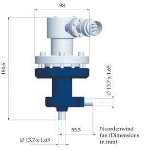
6) The CryoFans will be mounted partially inside and outside the cryostat/vacuum space. The pump housing (the dark blue part in Figure 4) with the connections to the gas lines (like VCR connections) will be inside the vacuum space. The motor with the shaft and impeller (gray part of figure 4) will be inserted from the top, from the outside of the vacuum space. This will enable the fan to be retracted from the system without breaking the vacuum, much like a cryogenic valve. It does, however, require a specific hole pattern. This can be made either in the wall off the cryostat or, for instance in a CF flange which then is mounted on the cryostat.
Please feel free to contact us if you have any questions or require additional information. www.d-h-industries.us/