by Mark Haynes, Paul Fabian and Michael Tupper, Composite Technology Development, Inc.
CTD has performed low temperature testing of structural elements for NASA’s James Webb Space Telescope (JWST). The testing, in association with the Goddard Space Flight Center (GSFC) and program prime and sub-contractors, was to minimize cost and risk of development efforts and to validate design performance under simulated operating conditions. Support of the JWST program involved a progressive building block approach, starting with simple materials and bonded joint tests, and followed by testing of sub-assemblies, prototypes and proof testing of flight hardware. Testing was conducted at temperatures ranging from 15K to 48K.
Test techniques required demonstration of accurate and uniform temperature control over the entire specimen, as well as uniform mechanical loading as evidenced by closely matching the output of numerous specimen-mounted strain gauges. Initial test results did not match anticipated performance but through a collaborative effort between structures and composites designers and the design of test fixtures, instrumentation configurations and test protocols, the final test results validated design expectations. This progressive building block approach, along with close collaboration between all parties, resulted in a lower cost approach to providing a low-risk and validated design of the JWST ISIM structure.
Background

The ISIM is a three-dimensional frame of 75 mm cross-section square tubes made of carbon fiber/cyanate-ester composite material, bonded together with gussets made of composite and clips made of Invar 36. The bonded composite/Invar assemblies must carry the 6500 kg launch loads at up to 5 G’s of acceleration and still perform to optical precision at cryogenic orbital temperatures. All four instruments must receive the same image concurrently, with a total distortion across the entire structure of less than 0.5 mm at the operational temperature of 40K, and a spacecraft survival temperature of 19K. The tube topology was driven by OTE and SI accommodation, specifically the need for stable attachment to the OTE near the primary mirror, stable attachment of the SIs near the light coming from OTE, and the limits of physical space available within the overall JWST architecture [1].
Approach
The progressive building block approach used in the JWST testing program and conceptually illustrated in Figure 2 built success upon success one step at a time towards successful completion of the project. Each design and each test had to be validated prior to moving on to the next, more complicated assembly. This increased the design confidence and made the analysis more “true to life,” ultimately saving money through reduced rework and redesign.
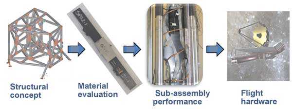
Specifically, the progressive building block approach used on this program started with lamina coupon samples to establish baseline properties of each of three carbon fibers—M55J, T700 and T300—with the selected resin system. After establishing the baseline properties, the testing moved to composite laminates with architecture that was a mixture of fiber angles and types. Once the laminate properties had been quantified, the focus moved to bonds between these laminates and Invar, using the double strap and flatwise tension tests to help define the need for primers and to determine how variations in manufacturing processes affected the bond strengths. An additional benefit of the laminate testing was the establishment of better methods of specimen alignment and verification of alignment at room temperature and liquid nitrogen temperature before using more costly liquid helium to cool the specimens to the final test temperatures.
Final test temperatures were between 15K and 45K, so reducing the costs of cryogens and minimizing the number of specimens that needed to be manufactured and tested at these temperatures were critical.
Additionally, the strain applied to different adherents in the double strap test was closely monitored to ensure that the bond joints were properly designed and were distributing the loads evenly.
Once the bonding processes and strengths had been established and validated, attention fell to the subassembly joint strengths. Each test had to be specific to each type of joint, with test procedures that mimicked the actual load paths expected in the spacecraft in order to validate the design of each bonded joint on the structure. Subsequent to the joint testing, proto-flight joint tests such as the one shown in Figure 3, which were similar to the subassembly joint specimens but included representative thermal masses and applied moments expected in flight situations, were performed. In some cases, CTD also provided thermal cycling and proof loading for flight hardware components.
Challenges

Solutions included changing outer plies, increasing strength and friction of specimen tabbing materials, and rebuilding of test fixtures with alloys more compatible with testing at cryogenic temperatures. In addition, test procedures were augmented to reduce alignment tolerances and to verify the temperature gradient throughout the entire specimen. Lessons learned in alignment and temperature control during less complex tests were applied to the larger, more complicated proto-flight tests, simplifying the test procedures, reducing test time and cost, and minimizing the number of specimens that needed to be tested.
Conclusion
Through CTD’s active role in the test planning, specimen and fixture design, test procedure protocols, and instrumentation, the design of the ISIM structure for the JWST was successfully shown to meet its challenging requirements. The ISIM structure has now been constructed and is undergoing a series of full-scale design validation and performance tests at NASA Goddard Space Flight Center. All tests performed to date on the ISIM structure have been completely successful. This is in a large part due to the extensive use of cryogenic testing as part of the progressive building block approach taken in the design of the ISIM structure.
References
1. Greenhouse, MA, et. Al., “Status of the James Webb Space Telescope Integrated Science Instrument Module System,” http://2csa.us/aa.