
The European Spallation Source (ESS) is an intergovernmental project building a multidisciplinary research laboratory based upon the world’s most powerful neutron source. The facility will be built in Lund, Sweden. The ESS will use a linear accelerator (linac), which will deliver protons with 5 MW of power to the target at 2.5 GeV, with a nominal current of 50 mA. Three separate cryoplants are foreseen to guarantee the necessary cryogenic cooling capacity for the entire facility.
The superconducting part of the linac consists of a total of 208 niobium cavities cooled with superfluid helium at 2K. The cryogenic hydrogen moderators in the target will operate at 17K to 20K under supercritical conditions. The test stand and instruments cryoplant combines liquefaction for the instruments at 4.5K and the occasional helium refrigeration for the cryomodule test stand. This article describes the baseline considerations, the conceptual design and the preliminary heat load estimates for the cryogenics of the ESS project.
The ESS facility
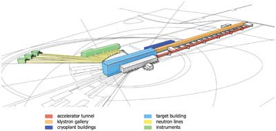
The ESS is a new international research facility to be built in the southern Swedish city of Lund. We are currently in the preconstruction phase [1] and will deliver first neutrons in 2019. Fully operational by 2025, ESS will deliver long-pulse intense neutron beams to 23 independent instruments. Figure 1 shows the general layout of ESS.
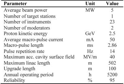
Table 1 shows the high level parameters. They set the baseline we will deliver and the fundamental framework in which we operate. For cryogenics, values such as beam power and proton energy are of course important, because most of the protons’ acceleration happens in RF cavities at 2K. But even values such as annual operating period and reliability have a strong influence on the design of the cryogenic system.
ESS’ cryogenic system serves three different parts of the machine, namely the linac, the target and the instruments. Each part has its own separate cryoplant. The target plant and its gas handling are completely isolated from the other two plants in order to allow containment of potential tritium contamination from the hydrogen circuit.
The linac cryoplant and the test stand and instruments cryoplants are separate processes, but share a common gas handling system. The separation of processes is necessary for several reasons. Firstly, the different parts of ESS have different installation schedules, and one cryoplant needs to be operational while the others are still being installed.
Secondly, we want to use the design, procurement and installation phases of the first cryoplant as a test and training opportunity to optimize our procedures for the following plants. Thirdly, operation of separate plants is much easier and more straightforward, compared to the multiple operational modes a single cryoplant would have to offer.
The linac cryoplant supplies liquid helium at around 2K to the superconducting RF cryomodules that make up most of the accelerator. The target cryoplant provides the helium refrigeration power at around 16K to the hydrogen moderators in the target. The test stand and instruments cryoplant supplies liquid helium in mobile dewars to experiments and instruments. This plant will also supply cooling to the cryomodule test stand for the site acceptance tests of the series production cryomodules and occasionally for R&D and maintenance of cryomodules during operation of ESS.
The Linac Cryogenic System
Figure 2 shows the general layout of the linac. The superconducting section is about 400 meters long and consists of 59 cryomodules. There are 14 spoke cryo-modules with two double-spoke cavities each, which take the beam to 191 MeV. There are 15 medium-beta and 30 high-beta cryomodules, each holding four elliptical cavities. They take the beam to the final energy of 2.5 GeV.

All cavities will operate at a helium bath temperature of around 2K. The operation temperature optimum is still to be determined by comparing the dynamic losses caused by surface resistance at radio frequencies—which are proportional to the helium bath temperature—with the increase in electrical power at the compressors of the cryoplant caused by the lower COP at lower client-side temperatures.
The cryogenic system for the ESS linac will mainly consist of one central cryo-plant and the cryogenic transfer line with a length of about 450 meters, supplying 4.5K helium at 3 bar to the cryomodules. Cooldown to 2K by JT expansion happens inside each of the cryomodules. Local 2K production and distribution at 4.5K significantly reduces the heat load at 2K, which justifies the increased equipment cost of the JT valves and heat exchangers in each of the cryomodules.
There are still a number of challenging issues to be solved in the conceptual design of the linac cryogenic system. Most importantly, we need to refine our heat load estimates for dynamic loads in the cavities. The total heat load of the linac is being dominated by dynamic losses in the cavities and power couplers. Their design is not finished, so exact calculations or even measurements are not possible yet. This is the biggest contribution to uncertainty in our estimates.
Our cryoplant’s cooling capacity estimate at a given temperature is based on the following formula:
C = Fo(FudQd +FusQs)
Where:
C = the total cooling capacity of cryoplant at a given temperature
Fo = operational safety factor
Fud = uncertainty factor on the dynamic heat loads (i.e. those associated with RF cavities and beam loads)
Fus = uncertainty factor on static heat loads
Qd= predicted dynamic heat load without any safety factor
Qs = predicted static heat load without any safety factor
The operational safety factor (Fo) takes into account the desirability of having some operating space in which to control the plant. It also allows some margin for seasonal temperature variations, and degraded plant performance. Fus and Fd take into account the uncertainty in predicting the exact static and dynamic heat loads.
Flow Schematic
The proposed schematic of the linac cryo distribution system has three cooling circuits. The primary circuit supplies 4.5K helium at 3 bar to the cryomodule. A heat exchanger precools the forward flow, followed by a JT valve to expand to saturation pressure at 2K.
The second circuit supplies a forced flow of helium to cool the RF power couplers. The helium warms up from 4.5K to ambient temperature towards the warm end of the power coupler and returns back to the cryoplant via a warm gas return line. The third circuit provides helium at about 14 bar to the 40-50K thermal radiation shield.
Each cryomodule will be connected to the cryogenic transfer line via jumper connections. The flow to and from the cryomodule is controlled via cryogenic valves situated in a vacuum insulated valve box on the transfer line. A vacuum barrier in the jumper connection separates the vacuum of the transfer line from the individual insulation vacuum of the cryomodule.
Linac Cryoplant
The linac cryoplant provides cooling at three temperature levels: 40 K – 50K for the thermal shields of the cryomodules and transfer line; 4.5K for the heat intercepts of the main RF power coupler and 2K for the cavities.
Our current estimate of the heat loads of the cryomodules and the distribution system is 1900 W at 2K, 1100 W at 5 to 8K and 13000 W at 40K. There is also an 8 g/s liquefaction load at 4.5K for cooling the main RF power coupler. These numbers do not include the safety factors discussed earlier.
If we apply typical safety factors, such as 1.5 for static heat loads, 1.75 for dynamic heat loads and 1.15 for operational margins, we can estimate the size of the linac cryoplant to be in the order of one of CERN’s 18 kW LHC plants, probably slightly smaller.
Target and Instruments
Besides the linac cryoplant, ESS will have two smaller plants—one for cooling the target hydrogen moderators and one for supplying the neutron instruments and their sample environments with liquid helium.
The moderators will use supercritical hydrogen at 20K and 15 bar to slow down the spallation neutrons before they reach the instrument lines. The neutrons, as well as gamma rays produced during the spallation process, will deposit significant amounts of energy into the hydrogen. This energy needs to be removed via a heat exchanger that will transfer the heat from the hydrogen circuit to a gaseous helium circuit. The helium is supplied by the target cryoplant
at 16K.
The concept is similar to the corresponding systems at SNS [2] and JSNS [3] as well as in larger hydrogen target experiments. The heat load for each of the two moderators is estimated at 10 kW (0.4 kg/s at 17-20 K) for the full proton beam power of 5 MW.
ESS’ purpose is to provide a tool to scientists where they can use the long-pulse neutrons to do their research into anything from semiconductors to enzymes. Especially in the life sciences, many samples need to be cooled to cryogenic temperatures, ranging from 80K down to a few microkelvin or even lower.
To help the sample environment specialists to achieve these temperatures, the cryogenics group supplies liquid helium in mobile dewars. The dewars are filled at the test stand and instruments cryoplant. The evaporated helium is recovered in a warm recovery line, purified and sent back into the process. This system reduces helium losses during normal operations to the absolute minimum. The projected necessary liquefaction rate is around 50 l/h, with significantly higher peak demands being supplied from a buffer dewar.
The instruments will also require up to 200 l/h of liquid nitrogen. This will be provided in mobile dewars from an on-site storage filled by an external vendor on a regular basis.
The instrument helium liquefier is also being used to supply refrigeration to the cryomodule test stand during the construction phase of ESS. Each of ESS’ 59 cryomodules will be tested under full RF load and at final cryogenic operating conditions prior to installation in the tunnel. Thus, the cryoplant needs to provide cooling at 40K, 4.5K and 2K, just like the linac plant.
Summary
ESS has embarked on an ambitious mission to design, build and operate the world’s leading neutron source for science. Our team of 140 dedicated people will grow to around 300 by the end of 2013. Groundbreaking is expected for 2014 and first neutrons for 2019. Like many other large science projects today, cryogenics at ESS forms an integral part of the facility, enabling the use of superconductors, ultra-cold hydrogen moderators and precisely cooled sample environments. The cryogenics team will expand over the next years in order to face the task of building three dedicated cryogenic systems. We’re looking forward to the challenges and to tackle them by collaborating with many institutes, scientists and engineers in the field of cryogenics and beyond.
References
- Peggs S. 2012, ESS Conceptual design Report.
- National spallation neutron source conceptual design report, Volume 1, 1997, Oak Ridge National Laboratory.
- Aso T., Tatsumoto H. 2006, Design result of the cryogenic hydrogen circulation system for 1 MW pulse spallation neutron source (JSNS) in J-PARC, Advance in Cryogenic Engineering, Volume 823: 763-770.