by Dr. Emanuela Barzi, Superconducting Strand and Cable Group Leader, FNAL, APS Fellow, barzi@fnal.gov
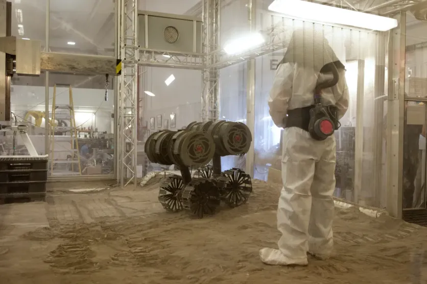
When construction of the new 6,000-square-foot industrial area at Fermilab was completed under ARRA funds in 2011, the main challenge of individuals in the Superconducting Strand and Cable R&D group of the Technical Division (TD) was to move their existing equipment from their smaller lab and assemble and install new equipment which had been procured and commission everything efficiently and safely.
By June 3, 2011, the previous lab was vacated, and its cryogenic and data acquisition equipment, cryo and vacuum pumps, as well as cable reels, assembly and metal tables, and several ovens were moved to the new area. The vacuum and vent piping was designed, procured and assembled, and the cryogenic equipment reconnected and operational. Minimizing downturn time was essential to keep serving the several lab and inter-lab projects that rely on this group, which had grown since 1997 around my research efforts on superconductors for accelerator magnets.
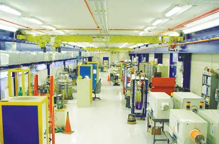
Behind the reaction site on the right side of the photo is a series of working areas devoted to superconducting sample preparation for reaction, superconducting sample mounting for testing on different experimental setups, tables for assembly of test fixtures, etc., as well as cabinets for storage of supplies, parts and samples. A motorized flat-rolling system to impart plastic strain within a desired range to round superconducting wires, usually before heat treatment, for superconductor studies is used in this area. On the closest end of the building, not shown, on the left, is a large storage area of reels of superconducting cables.
The cabling facility, which is conveniently located in the attached building IB3, includes a compact cabling machine with 42 spools and electronic synchronization for lay angle control, a re-spooler, sets of forming fixtures, mandrels and measuring devices. Rutherford-type and round cables have been fabricated with and without stainless steel core, out of both conventional conductors like Cu and Ag and superconducting round wires, including NbTi, Nb3Sn, Nb3Al, MgB2 and Bi-2212.
Teslatron 1, 2 and 4 house high field superconducting solenoids having respectively 15 T/17 T, 14 T/16 T and 8.5 T/10 T fields and 64 mm, 77 mm and 147 mm cold apertures, whereas Teslatron 3 is just a cryostat that was used to test HTS helical coils. Teslatrons 1 and 2 are equipped with vacuum insulated anti-cryostats, which save helium and can be used to perform variable temperature measurements between 1.5K and 300K. Current capabilities range from 1875 A to 2400 A. DAQ systems include current, voltage, temperature, magnetic field and helium level readings, as well as quench protection, with Teslatron 2 also being equipped with an integrator for magnetization measurements and a Rogowski coil for current measurements. Not shown is a low temperature cell loader to perform strain gauge calibration both at room temperature and at 4.2K.
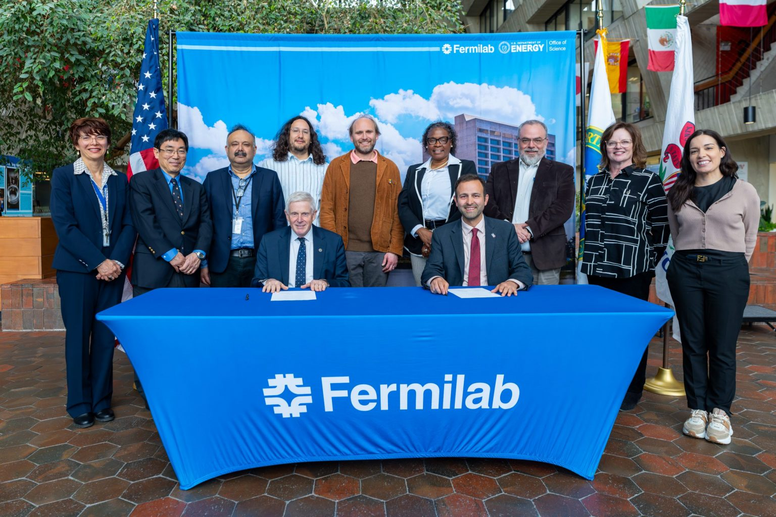
At the end of 2011, Technical Division Head Giorgio Apollinari had called for a cryogenic review of the whole lab by a Cryogenic Safety Panel chaired by Terry Tope. What ensued was a large team effort that involved the group members shown in Fig. 3 and several others who worked in conjunction with the panel. While Miao Yu was working on an engineering note for the cryogenic piping system, later reviewed by Mayling Wong and Tom Peterson, Ali Hemmati and Roger Rabehl took care of the ODH analysis. I pitched in on pressure vessel engineering notes and calculations for the magnetic cryostats, while Al Rusy contributed on P&ID and layout drawings, and on procedures. Deputy group leader Dan Turrioni, an electronics engineer, was charged successfully with performing an ODH analysis for the large vacuum pump shed, while Vito Lombardo organized the documentation for the panel and interacted with vendors to obtain requested information. Tom Nicol and Steve Krave performed the calculations needed for the cell loader. Hazard analyses were brainstorming team efforts. All the while, testing activities continued under the care of Tom VanRaes, Marianne Bossert and James Karambis.

Other experimental setups include a balanced coil magnetometer to measure magnetization of conventional (iron) and superconducting materials (bulk Nb, Nb-based multifilamentary superconductors, etc.) between 0 and 15 T and at temperatures between 1.5K to 300K, a device to test critical current sensitivity of impregnated superconducting cables to uniaxial (plane stress) transverse pressures up to 200 MPa, and a superconducting transformer for Rutherford cable tests and cable splice studies up to
28 kA in self-field.
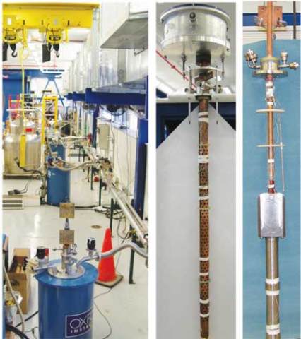
A modular Insert Test Facility was designed to use Teslatron 2 to test individual double pancake units made of 2G YBCO, and a four double pancake coil that produced a maximum field in the YBCO of 21.5 T. The latest additions to this arsenal are shown in Fig. 2. At center a Walters’ spring-type device for tensile/compressive strain sensitivity studies of Jc in superconducting wires is shown, which was recently calibrated and commissioned using Nb3Sn and Nb3Al state-of-the-art wires. At right is a 14 T/16 T Rutherford cable test facility with a bi-filar sample and a superconducting transformer which has recently been upgraded to a cable current of 25 kA.
The mission of the Superconducting Strand and Cable R&D program is to understand and improve scientific and engineering aspects of superconducting strands and cables for accelerator magnets, including dipoles, quadrupoles and solenoids. This is performed in synergy with the Superconducting Magnet Group led by Alexander Zlobin, to provide conductor specifications and essential engineering data for magnet design and construction. Coordination of work with industry has been improving performance of LTS strands and cables, and collaboration with other laboratories and universities has been contributing to fundamental understanding of strands, cables and magnets. This activity plays a key role and has the potential for very high impact on the future Energy Frontier programs in the US and worldwide, including luminosity and energy upgrades for the LHC as well as the construction of new machines such as the Muon or new Hadron collider.
Since 1998, the Superconducting Strand and Cable R&D Lab has also served as the ideal experimental environment for 30 graduate students in physics and engineering to receive hands-on training in superconductivity, strain theory, heat transfer, cryogenics, mechanical design, electronics, computing and automation during summer internships or Specialized Laurea and PhD theses.