by Stuart Watson, Airbus Defence and Space, stuart.watson@astrium.eads.net and Dr. Adam L. Camilletti, Airbus Defence and Space, adam.camilletti@astrium.eads.net
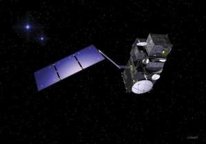
The Sentinel 3 satellites are part of the European Space Agency’s (ESA) Copernicus program for global monitoring for environmental and security purposes. The spacecraft, manufactured by Thales-Alenia Space France (TAS-F) are tasked with measuring sea surface topography, sea and land surface temperature and color with high accuracy and reliability. To do this, it is equipped with two instruments. To perform the temperature measurements, the Sea Land Surface Temperature Radiometer (SLSTR) is fitted.
The SLSTR, being produced by Selex ES, Italy, is capable of measuring surface temperatures to an accuracy of less than 0.3K at a resolution of down to 500 m. To achieve this, the instrument’s optical assembly and sensors must be cooled to below 85K. This, combined with a mission life of more than 7.5 years, is where the need for a mechanical cryocooler system (CCS) comes from.
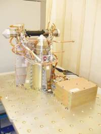
The Airbus DS CCS can be broken down into three distinct sections:

The 50-80K Stirling cooler is of split-cycle configuration, with a 300 mm transfer line linking the compressor and displacer assemblies. The linear compressor is of typical Oxford-type design, with a moving coil supported between two sets of flexure bearings, or diaphragm springs as they are also known. These bearings see more than 10 billion deflections during life and therefore special precautions must be taken to prevent the possibility of fatigue failures. These include photochemical etching rather than conventional machining and individual part inspection.
Mechanically, the displacer is of the same design as the compressor but on a smaller scale, reflecting its reduced power consumption. Dynamic gas seals are of the clearance type, with clearances on the order of five microns made possible by the flexure bearings’ high radial stiffness. Position monitoring is provided by linear variable differential transformers and the working fluid is helium-4.

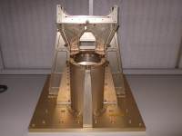
Linking the 50-80K Stirling coolers and the instrument are two thermal link assemblies, supplied by Space Dynamics Lab, Utah. These were specially developed for the project from Space Dynamics’ existing range, and are of the aluminium foil type. Cold tip monitoring is achieved through use of Cernox sensors.
Due to its close proximity to the instrument, a tight exported vibration limit was placed on the CCS. This has been achieved through pairing the mechanical coolers’ mechanisms and placing them in opposed orientations. Active control is provided through the use of Kistler 8203A50 piezoelectric accelerometers, which provide feedback to the drive electronics. These were specially space-qualified for this system.
The CDE incorporates a number of closed-loop control algorithms. As well as controlling mechanism motion, the CDE can be ordered remotely to control cold tip temperature and mechanism stroke and to actively minimize self-induced vibration. Other CDE functions are conditioning high accuracy thermistors and accelerometers; built-in protections to prevent over-stroke or over-current events within the 50-80K Stirling coolers, and a diagnostic capability that allows in-flight health checking of the cryocooler mechanisms.
The overall system is designed to run in a hot redundant mode: Both coolers are nominally run at approximately half power to achieve the required lift. Should there be a failure in one side of the cooling chain, the other side is then ramped up to full power to partially compensate. In addition to featuring two separate cryocoolers, all sensors on the CCS are installed in primary and redundant pairings.
In order to meet ESA standards and qualify the CCS for space flight, a full environmental test program has been run. The system has been vibrated to the levels generated by the launch vehicle and thermally cycled between survival temperatures of -40˚ and 60˚ C. At the completion of this test program, the system was confirmed capable of providing a 1.5W heat lift at 78K with a rejection temperature of 20˚ C and an electrical power supply of 80 W.
To contact the Cryocooler Engineering and Development Group at Airbus Defence and Space in the UK, please contact stuart.watson@astrium.eads.net or adam.camilletti@astrium.eads.net.
This work was produced with the financial assistance of the European Union. The views expressed herein can in no way be taken to reflect the official opinion of the European Union.