
by Michiel van Limbeek, Cris Vermeer, and Marcel ter Brake, University of Twente. Romaine Kunst, Adrie Visser, Pieter Lerou, and Erik-Jan de Hoon, Demcon kryoz. Johannes Burger, Martijn Al, and Hassan Firouzbakht, Cooll.
The Einstein Telescope (ET) will be the first third-generation gravitational wave detector, marking a new era in gravitational wave science. To detect relative length changes smaller than 10⁻²², one of the most revolutionary technologies in ET is the cryogenic system which will cool the main optics to approximately 10 K. Considering the extreme sensitivity targeted by third-generation laser interferometers, it is essential that this cryogenic cooling operates continuously with ultralow vibration levels in order to minimize thermal noise.
To address these stringent vibration requirements, a new sorption-compressor-driven Joule-Thomson cryocooler has been developed by a consortium of University of Twente, Demcon kryoz, and Cooll Sustainable Energy Solutions. The system features a vibration-free, three-stage cooling architecture using sorption compressors and Joule–Thomson expansion to reach a temperature down to 8 K, without any active mechanically moving parts.
The sorption-compressor-driven Joule-Thomson cryocooler has been developed for the ETpathfinder (ETPF) project. The ETPF facility is a scaled testbed for the development and demonstration of key enabling technologies for ET. Construction started in 2025 at the University of Twente and Demcon kryoz, with validation taking place at the University of Twente in the summer of 2026. The first integration steps into the ETpathfinder setup are expected by late 2026, marking a significant realization step towards meeting the requirement for ET. The vibration requirement at the cold finger is exceptionally demanding: seismic excitation has been measured at the ETpathfinder site with an amplitude spectral density of 4 nm /√Hz in the frequency range of 2-10 Hz.[1] The amplitude spectral density indicates not only how much an object is vibrating, but also helps to understand which frequencies are contributing to that vibration. The measured amplitude spectral density corresponds to a peak-to-peak displacement of 32 nm. This vibration level cannot be exceeded by the sorption-based cryocooler. To put that into perspective, a human hair has a thickness of 50 µm. Although challenging, the strong heritage in sorption-based cryocooling in Twente (The Netherlands) provides a solid foundation for the development of this innovative cryocooler, and the consortium’s combined expertise ensures confidence in reaching the required technology readiness level (TRL 6–7) within the given timeframe of three years from the Dutch National Growth Fund. The roadmap of this technology is displayed in Figure 1.

The resulting system is a three-stage sorption-based Joule-Thomson (JT) cryocooler using neon, hydrogen, and helium stages to achieve an available cooling power of 50 mW at a temperature of 8 K at the cold tip of the cryocooler. The helium stage functions as a heat sink to cool the mirrors, the main optics in the interferometer. The hydrogen and neon stages provide intermediate cooling to reduce radiative heat loads and provide cooling power to the helium stage. Based on its design, the system is expected to remain well below the specified vibration levels.
This article first explains the architecture of the cryogenic cooling system, including the rationale behind key design choices. It then describes the systems engineering approach and modeling activities used to verify compliance with the requirements for cooling power, temperature and cooldown time. Finally, part two of this article will address the fundamental research and mitigation strategies implemented to achieve the most stringent requirement: extremely low-vibration levels.
System Overview
For every new gravitational wave detector, the aim is to improve sensitivity. To achieve that, various noise levels have to be reduced overall. The reduction of thermal noise was first addressed in the latest gravitational wave detector, KAGRA. Thermal noise reduction allows for a higher sensitivity in the low-frequency domain. Cryogenic temperatures of 20 K are achieved in KAGRA in a high-vacuum environment by using multi-stage pulse tube cryocoolers. However, for the Einstein Telescope, the aim is to further increase sensitivity. For example, an increased sensitivity of three orders of magnitude at 5 Hz compared to KAGRA is foreseen. Achieving cryogenic temperatures while meeting the stringent vibration requirements at the cold tip demands a cooling solution that introduces virtually no vibrations at the cold finger. Conventional mechanical cryogenic coolers — such as Stirling, “pulse tube,” mechanical Joule-Thomson (JT), and Gifford-McMahon (GM) coolers — rely on moving mechanical components, which inevitably generate and transmit vibrational noise to the payload. To achieve a higher sensitivity than the latest detector, there is a need for a new cooling solution.
Working Principle of Sorption-based Joule-Thomson Cold Stages
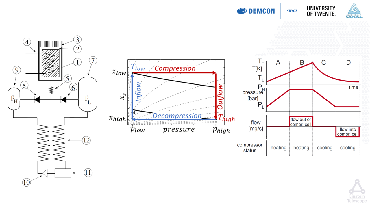
A fundamentally different approach is needed, which the Twente sorption-based JT-cryocooler of-fers. In this concept, JT-cold stages based on the Linde-Hampson cooling cycle are driven by sorption compressors. Figure 2 illustrates the basic architec-ture of a sorption-based JT cryocooler. The system comprises a sorption compressor cell, two buffer volumes, and two passive valves.
System Design around Sorption-based Joule-Thomson Cold Stages
To maintain the cold tip at approximately 8 K with minimal vibration, the design avoids any phase change at the cold tip, which dictates the use of helium as the working fluid for the final stage. Helium will be operated in single gaseous phase, which is not an option for the hydrogen stage, since hydrogen is in the solid phase at 8 K. Achieving this requires multiple subfunctions within the cooling cycle:
- Pressure Management: High and low pressures must remain stable to ensure sufficient cooling power and mass flow. This is achieved first by operating the heating time of multiple cells out of phase. This stabilizes the outflow of the compressor. Final pressure regulation is achieved by the high and low pressure buffer that further dampen these flow fluctuations.
- Thermal Management: To cool the mirrors of the interferometer, flexible heat links will transfer the heat from the mirror towards the helium cold tip. Because helium alone cannot provide the required cooling power of 50 mW at 8 K, additional stages are required. The system therefore employs a three-stage architecture in which all stages are thermally linked via intercoolers:
○ Stage 1 (Neon): The neon stage cools the intermediate radiation shield and precools the helium and hydrogen cold stages at 35 K. Provides initial cooling and cools an outer radiation shield.
○ Stage 2 (Hydrogen): The hydrogen stage cools the innermost radiation shield and precools the helium cold stage at 18 K. The intercooler of the hydrogen stage determines the precooling temperature of the helium stage.
○ Stage 3 (Helium): Achieves the final 8 K at the cold tip.
The heat will be transported through this cascade configuration through the hydrogen and neon stage towards the liquid nitrogen bath, the backend cooling source of this cooler. The ultrahigh vacuum (UHV) environment inside the mirror tower will eliminate convective losses.
- Shielding Strategy: A liquid nitrogen bath cools the the 77 K shield and the floating shield, which intercepts radiative heat load from the 300 K external environment. Inside this area are two additional actively cooled shields, one cooled by the neon stage and one cooled by the hydrogen stage. These shields will reduce the radiation heat load onto the helium cold tip. This configuration minimizes heat loads on the optics while maintaining mechanical isolation.
The helium cold stage has a cooling power of 50 mW, however; to cool the system down from room temperature to cryogenic temperatures will take weeks because of this low cooling power. Therefore, for the initial cooling down process of the system, an additional kickstarter system is introduced. This auxiliary system is a Gifford-McMahon cryocooler that provides high cooling power of 250 W during the initial phase, rapidly removing heat from the large thermal masses. Once the system reaches cryogenic conditions, the kickstarter is fully disconnected and the sorption cryocooler takes over ensuring vibration-free operation for the remainder of the process. This staged approach results in a total cooldown time of less than seven days.
Look for Part 2 of this feature in the next issue of Cold Facts.
References:
To view full list of references, visit https://2csa.org/rj0