by Nils Tellier, PE, President, EPSIM Corporation (CSA CSM)
nils@epsim.us
All illustrations courtesy EPSIM Corporation
Background History of Air Separation and Liquefaction
This section builds on a rich history of methods to develop deep refrigeration and cryogenic liquefaction during the 19th Century. You are encouraged to read Cryo Central’s History of Cryogenics for more information.
In 1902 George Claude improved the refrigeration cycle by adding an expansion engine and a mechanical brake to reduce the enthalpy of the air vapor, and therefore its temperature, at nearly constant entropy. The idea had first been proposed by Carl Siemens in 1857 and attempted by Ernest Solvay in 1885. The isentropic expansion resulted in a dramatic reduction in cooling time and operating pressures, while increasing the throughput of liquefied air. George Claude founded Air Liquide that year. 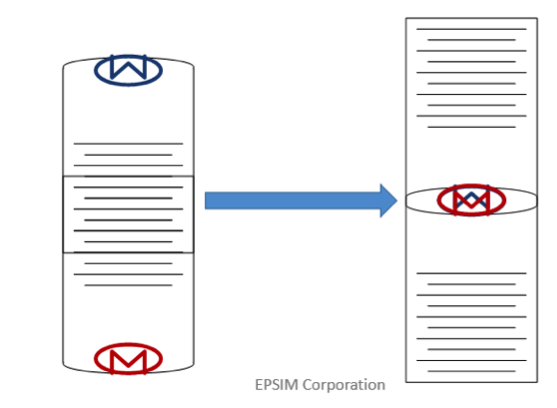
One more significant refinement leading to the modern cryogenic air separation and gas liquefaction industry was to replace the piston expansion engine by a more efficient turbo-expander technology. Credits go to Guido Zerkowitz (Linde AG) in 1935 and Pyotr Kapitsa in 1939.
Modern Air Separation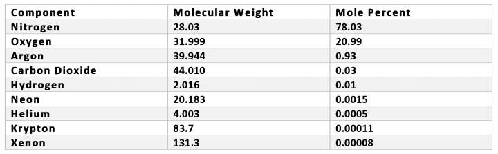
There are different techniques to extract—or concentrate—a component from the air. Hollow fiber membrane systems and pressure-swing adsorbers are two non-cryogenic means to extract nitrogen; vacuum-swing or pressure-vacuum swing adsorption, and ceramic membrane ionization are also used to produce oxygen. However, these processes are outside the scope of our presentation.
Air Filtration and Compression
Atmospheric air is first filtered to remove airborne particles before it enters the Main Air Compressor. The compressor is the main energy user in an air separation plant. It is a significant determinant of electricity costs and costs per ton of the products oxygen, nitrogen or argon. The purpose of the compression step is to control the mass flow of air feeding the cryogenic distillation column at the condenser/reboiler operating pressure. When the air separation plant is in steady operation, it is the condenser/reboiler that pulls the air. The compressor then regulates the air flow and the balance act determines the operating pressure. 
Centrifugal compressors will surge when flow is reduced below a certain point at a given pressure. To prevent this, a surge controller measures in real time two independent variables, such as the discharge pressure and the flow or motor amps. When the controller sees that the compressor approaches its surge curve, it will open a recycle valve—a vent in the case of an air compressor—to increase flow. A second control, used to operate the entire air separation plant, is the air flow control from the compressor’s inlet guide vanes. The air flow variable is mass flow, where the volumetric air flow measurement is compensated in real time for temperature and pressure. Flow and pressure instrumentation on the compressor must be installed with wet saturated process air in mind, in a manner that moisture does not accumulate in low points of the instruments’ tubing.
Air Purification
The purpose of the purification step is to remove all traces of moisture and CO2 from the high pressure oil-free air. There are two alternatives to accomplish this: front end purification by adsorption, and reversing heat exchangers (REVEX).
In contrast, front-end purification is considered state-of-the-art for air purification. It entails two or more adsorber vessels filled with activated alumina and molecular sieve. Alumina retains all the moisture from the air. The molecular sieve, typically 13X, removes the CO2 and several hydrocarbon contaminants. One vessel is one line cleaning the air while the other vessel is being desorbed with dry nitrogen byproduct from the air separation plant. The vessels are sized to switch every four to eight hours. Although molecular sieve retains water, perhaps better than alumina, it only desorbs it at very high temperatures and requires a plant shutdown for an exceptional reactivation. High pressure air leaving the front-end purification is absolutely free of moisture and CO2, and is called Clean Dry Air (CDA).
The “Cold Box” and Cryogenic Distillation
The high-pressure, oil-free air, cleaned of moisture and CO2 traces, enters a “cold box” which houses the super-insulated cryogenic equipment. The cold box includes cryogenic heat exchangers, distillation columns, the turbo-expander and all the cold piping, carefully insulated with rockwool or perlite, and boxed in a carbon-steel outer jacket. Cryogenic cold boxes often appear as tall white structures, deceptively void of any outside feature. 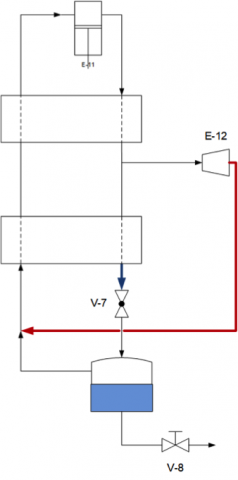
To further compensate for parasitic heat leaks and liquid production, additional refrigeration is provided by a turbo-expander following a Modified Claude refrigeration cycle. The expander inlet is located at the “midpoint” of the main exchangers, namely at the piping junction between the warm and the cold exchangers.
Plant efficiency can be measured by the exchangers’ approach temperatures at the warm end and at the cold end. A small temperature difference at the warm end shows good thermal efficiency, or low heat losses. Likewise, a small temperature difference at the cold end is a sign of good oxygen recovery. However since the air enthalpy does not add up to that of the product gases (oxygen and nitrogen), the cold end and warm end approach temperatures are mutually disruptive: reducing the cold end temperature difference increases the warm end one and vice-versa. A benefit of the Claude refrigeration cycle is that the expander increases the temperature difference at the midpoint and thus closes the approach temperatures simultaneously at the process warm and cold ends.
The air leaving the cold end of the main exchangers is close to its liquefaction point of -160°C (-260°F). It enters the lower distillation column, also called the high-pressure column or HP column—and nowadays referred to as Medium-Pressure column. Air vapor entering the HP column is pulled upward across distillation trays or packing by the condenser/reboiler located at the top of the column. Since the saturated air density increases by a factor of 35 when it turns from vapor to liquid, it is easy to visualize the force of the convection happening inside the HP column. The rising vapor is gradually stripped of oxygen by the falling liquid, by fractional distillation across the column trays or packing sections, such that the top of the HP column sees only pure nitrogen. Nitrogen production, gaseous or liquid, comes from the HP column head. The column sump holds a “rich liquid” composed of nitrogen, argon and approximately 35 percent oxygen. The rich liquid is expanded into the upper column as feed and a stream of liquid nitrogen from the top of the HP column is sent to the upper column as lean reflux. 
Gibb’s Law tells us that there is a direct relationship between pressure and temperature for a two-phase fluid of known composition. Hence by controlling the pressure at the top of the HP column we also control the condensing temperature of the HP nitrogen. Conversely, controlling the pressure at the sump of the LP column gives us control of the boiling temperature of the LOX bath. In summary, the temperature difference—and duty—at the condenser/reboiler is a function of the pressure ratio between the lower and upper columns.
This brings us to the upper column where further distillation takes place to purify the oxygen and, as the case may be, extract argon for further purification. The upper column operates at a low pressure, as close to atmospheric as possible. It is called the low-pressure or LP column. If we take into account the pressure drop across the main exchangers and some driving pressure to utilize the nitrogen byproduct for the regeneration of the air cleaning system, pressure in the LP column determines the HP column pressure required for the condenser/reboiler to work, which in turn determines the main air compressor discharge pressure. It is therefore more economical energy-wise to operate the LP column at the lowest possible pressure.


In the 1990s became increasingly common to pump the LOX at high pressure into the main exchangers, where the oxygen is vaporized and warmed against incoming air. This process is very efficient, because liquid pumping does not create heat of compression and a two-phase fluid cools the incoming air by leveraging the latent heat of vaporization in addition to its sensible heat. Figure 9 illustrates the cryogenic equipment inside a cold box for a gaseous oxygen plant with pumped LOX.
What about argon, which makes up nearly one percent of the air? Argon is particularly challenging because it is very close to oxygen in molecular weight and bubble point. The O2-Ar phase diagram is very flat, which requires a very tall distillation column. Adding insult to injury, argon freezes and blocks process equipment at relatively “warm” temperatures. Squeezed between the boiling LOX and the cold reflux in the LP column, argon concentrates to about 30 percent near the center of the column where it is extracted and further purified in separate columns. Modern plants post 1992 are able to purify argon in a single column located next to the LP column. Argon is produced and marketed as a liquid.
In summary, the cryogenic separation of air to produce oxygen and nitrogen requires constant and simultaneous heat and mass balances. Cooling down an air separation plant from ambient conditions can take up to two days, usually following a week of cleaning or “deriming” the cold box internals. Loss of efficiencies in the process translate into higher power consumption by the main air compressor and thus higher production costs. Modern and retrofitted plants are highly automated in order to maintain efficient and robust operations with runtimes between scheduled shutdowns upwards of 35,000 hours.
A closing remark, perhaps the most important topic, is that of safety. Cryogenic temperatures, nitrogen and oxygen present safety hazards. Additionally, process air contamination from oil and hydrocarbons can combust spontaneously with oxygen. There are many safety features in the design and fabrication of an air separation plant, including hydrocarbon detection and control, oxygen cleanliness, oxygen velocity control and choice of materials of construction.